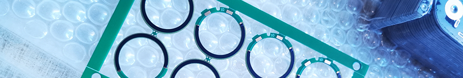
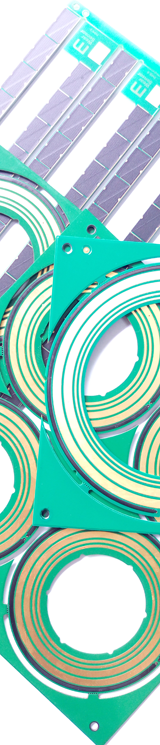
Rotary Position Sensor PCB
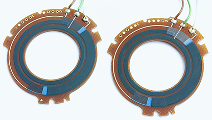
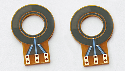
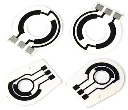
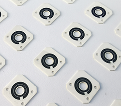
Rotary Position Sensor PCBs are customizable, high-precision electronic circuits designed to measure rotational displacement or angle, integrating thick film resistors (usually in circular resistor tracks) into the printed circuit board to utilize resistance changes caused by the rotation of components (wipers) for accurate measurements, making them ideal for applications requiring precise position sensing and widely used in motor control, steering systems, potentiometers, robotics, and angle measurement devices, providing stable and precise feedback to ensure reliable operation in high-performance, highly integrated environments. Rotary Position Sensor PCBs, also referred to as Rotary Displacement Sensor PCBs, are used to detect the angular position of a rotating shaft or object, where the voltage divider value can be measured at any position of the carbon resistive track by means of sliding wipers between the applied voltage values. The carbon paste is printed on two terminals at opposite ends of the circuit, forming one or more voltage dividers on the PCB, After mounting with the sliding wiper, housing, slider block, the shaft and the bearing, resulting in a rotary position sensor. Rotary Displacement Sensor PCBs provide all the functions of a rotary potentiometer, which is equivalent to transplanting or integrating the potentiometer module onto the PCB surface directly, Rotary Position Sensor PCB technologies could not only effectively save the assembly space of the products, but also provide a variety of options for position sensor developers, The most important thing is to reduce the manufacturing cost effectively. Main Features of Rotary Position Sensor PCB : |
 |
|
 |
1, Integration: The Rotary Position Sensor PCB seamlessly integrates a rotary potentiometer into its design, allowing for easy incorporation into electronic systems and devices. 2, Contacting Device: This PCB incorporates a circular resistive track and a wiper attached to the center shaft, creating a precise contacting device for accurate angular displacement measurement. 3, Voltage Variance: As the shaft rotates, the wiper maintains contact with the resistive track, resulting in an output voltage variance that is directly proportional to the angular displacement. This allows for precise and reliable measurement of position or rotation. 4, Consistent Voltage: The Rotary Position Sensor PCB ensures a consistent and stable supply of voltage to the potentiometer, enabling accurate and repeatable measurements. |
|
5, Full 360-Degree Rotation: Designed as a voltage divider, this PCB enables a complete 360-degree rotation, facilitating the measurement of all angles during a full turn. This feature is particularly useful in applications where continuous rotation needs to be monitored or controlled. 6, Versatility: The Rotary Position Sensor PCB finds extensive use in various applications requiring angular position sensing and control. It is commonly employed in robotics, automotive systems, audio equipment, industrial machinery, and other precision control systems. 7, Customization: This PCB can be customized to meet specific requirements. Parameters such as resistance values, shaft lengths, mounting options, and form factors can be tailored to suit the application's needs. 8, Compact Design: The Rotary Position Sensor PCB is designed to be compact and space-efficient, making it suitable for applications with limited available space. 9, Durability: Built to withstand mechanical stress and environmental conditions, this PCB offers robustness and longevity in operation. It ensures reliable performance even under demanding circumstances. Rotary Position Sensor PCB offers accurate position sensing, compact design, cost-effectiveness, and versatility, making it a valuable component in many rotating machinery and equipment systems. Please refer to Thick Film Potentiometer PCB for more informations. |
||
Applications of Rotary Position Sensor PCB : |
1, Robotics: In robotics, the Rotary Position Sensor PCB is employed for joint angle sensing in robotic arms, providing feedback for precise control of movement and positioning. 2, Automotive Systems: Within automotive systems, these PCBs are used for throttle position sensing, suspension system monitoring, and steering angle measurement to ensure optimal vehicle performance and safety. |
|
 |
3, Audio Equipment: Rotary Position Sensor PCBs are integrated into audio equipment such as mixers, amplifiers, and equalizers to control volume, balance, and tone adjustments. 4, Industrial Machinery: They are utilized in industrial machinery for position feedback in automated manufacturing processes, as well as for controlling the movement of mechanical components. 5, Consumer Electronics: Applications in consumer electronics include use in knob-based controls for appliances, entertainment systems, and other electronic devices where precise user input is necessary. 6, Aerospace: In aerospace and aviation, Rotary Position Sensor PCBs are utilized for flight control systems, throttle positioning, and actuator feedback mechanisms. 7, Medical Devices: These PCBs play a critical role in medical devices for applications such as patient positioning systems, surgical equipment, and diagnostic instruments that require accurate angle measurement. |
8, Renewable Energy Systems: Within wind turbines and solar tracking systems, Rotary Position Sensor PCBs are utilized to monitor and control the orientation of solar panels and wind turbine blades for optimal energy capture. 9, Gaming Controllers: They are incorporated into gaming peripherals such as joysticks and steering wheels to provide accurate and responsive user input for gaming experiences. 10, Control Systems: In general control systems for industrial, commercial, and consumer applications, Rotary Position Sensor PCBs are used for position feedback and control of various mechanical and electromechanical systems. |
|
Contact VS Non-Contact of Rotary Position Sensor PCB: |
In the realm of Rotary Position Sensor PCBs, the traditional Rotary Potentiometer PCB (contact-based) stands apart from other non-contact sensor PCBs in several key aspects, including manufacturing processes, materials used, operating principles, advantages, and disadvantages. Let's delve into the comparative analysis: 1, Manufacturing Processes: 2, Materials Used: |
|
 |
3, Disadvantages: 4, Resolution: |
5, Operating Principles: 6, Advantages: |
|
 |
7, Durability: 8, Response Time: |
9, Environmental Sensitivity: 10, Application Specific Considerations: |
|
Design Considerations of Rotary Position Sensor PCB : |
1, Mechanical Design: |
|
 |
2, Electrical Design: 3, Signal Integrity: |
mismatch, and electromagnetic interference (EMI). 4, Environmental Considerations: 5, Manufacturing and Cost Optimization: |
|
Materials Selection of Rotary Position Sensor PCB : |
Substrates |
Advantages |
Disadvantages |
|
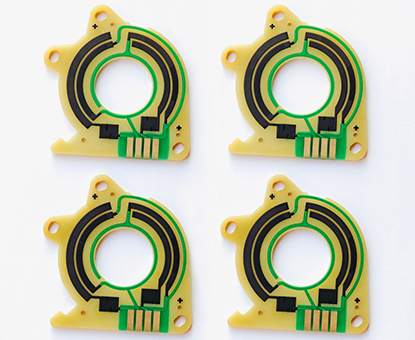
FR4 |
|
● Cost-Effectiveness: FR4 is the most common PCB substrate material, and due to its widespread use, it is relatively low in cost. ● Good Electrical Properties: FR4 has good insulation and mechanical strength, making it suitable for most electronic applications. ● Easy to Process: FR4 is easy to manufacture and fabricate, compatible with various PCB production techniques. |
● Limited Heat Resistance: Although FR4 can operate at higher temperatures, it has lower heat resistance compared to ceramic substrates. ● Relatively High CTE: This can affect the stability of the circuit under temperature changes. |
Ceramic |
|
● High Thermal Conductivity: Ceramic substrates have excellent thermal conductivity, which is helpful for heat dissipation and suitable for high-power applications. ● Good Electrical Insulation: Ceramic materials have high electrical insulation properties, making them ideal for high-frequency circuits. ● Thermal Stability: Ceramics have a low coefficient of thermal expansion, making them suitable for operation under extreme temperatures. |
● Higher Cost: Compared to FR4, ceramic substrates are more expensive. ● Processing Difficulty: Due to the high hardness of ceramic materials, they are more difficult and costly to process. |
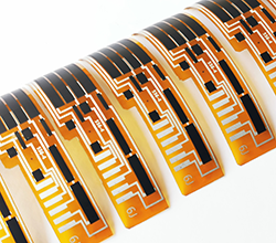
Flex PI |
|
● Flexibility: PI substrates have good flexibility, making them suitable for applications that require bending or curling. ● High-Temperature Resistance: PI substrates can operate stably in high-temperature environments. ● Chemical Resistance: PI substrates have good resistance to a variety of chemicals. |
● Higher Cost: The cost of PI substrates is usually higher than that of FR4. ● Electrical Properties: Although PI substrates have excellent mechanical properties, their electrical properties may not be as good as those of ceramic substrates. |
When selecting a substrate material for Rotary Position Sensor PCBs, it is necessary to balance the specific requirements of the application and the budget. For instance, if the application requires high power handling and excellent heat dissipation, ceramic might be a better choice. If considering a balance between cost and electrical performance, FR4 might be a more suitable choice. For applications requiring flexibility, PI substrates are the ideal choice. |
|||
How Important of Linearity in Rotary Displacement Sensor PCB ? |
1, Position Sensing Accuracy: |
|
 |
2, Signal Consistency and Predictability: 3, System Calibration and Control: 4, Performance in Feedback Systems: |
5, User Experience and Product Quality: 6, Design Considerations: |
|
Multi-Wire Wipers Used For Rotary Position Sensor PCB : |
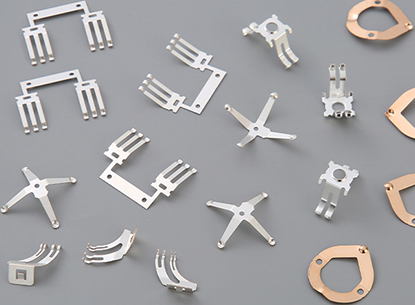 |
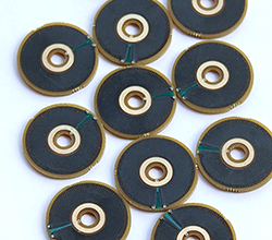
Multi-Wire Wipers are commonly used in rotary position sensor PCBs. These wipers consist of multiple wires or fingers that make contact with the resistive element as the control shaft rotates. The number of wires or fingers used determines the resolution of the position sensor. Generally, the more wires/fingers there are, the higher the resolution and accuracy of the position sensor. Multi-wire wipers ensure that there is constant contact with the resistive element, resulting in a smooth and precise output signal. Multi-Wire Wipers are crucial components designed to transmit voltage and signals. They perform linear or rotational sliding over the surfaces of resistive materials (thick film resistors) to adjust resistance values and act as contact elements in voltage dividers. Wiper design is extremely critical for the efficiency and life of the sensor assembly, When designing the wiper, it is very important to consider contact resistance, working-hight (load), repeatability, hysteresis, the resistive material used, and in particular, the wiper material itself, its shape and the wiper pressure. |
We also provided custom Multi-Contact Wipers for customer if needs, we can manufacture the wipers according to customer's design requirements or specification, For more information about wipers, Please refer to Multi-Wire Wipers. |
|
Engineering Specification of Rotary Potentiometer Sensor PCB : |
Items : |
Typical Values |
Advanced Capabilities |
1, Substrates : |
FR4, Ceramic ( AI203, ALN, BeO, ZrO2), Polyimide (Flexible PI), Stainless Steel (SUS304), Mica |
FR4, Ceramic ( AI203, ALN, BeO, ZrO2), Polyimide (Flexible PI), Stainless Steel (SUS304), Mica |
2, Conductor (Paste) Materials : |
Copper, Silver , Gold , Silver-Palladium, Palladium-Gold, Platinum-Silver, Platinum-Gold |
Copper, Silver , Gold , Silver-Palladium, Palladium-Gold, Platinum-Silver, Platinum-Gold |
3, Thick Film Carbon Thickness (Height) : |
15um +/-5 um |
30um +/-5 um |
4, Conductor Thickness (Height) : |
12um+/-5um |
20um+/-5um |
5, Min Width of Thick Film Line : |
0.30 mm +/-0.05 mm |
0.20 mm +/-0.05 mm |
6, Min Space of Thick Film Line : |
0.30 mm +/-0.05 mm |
0.20 mm +/-0.05 mm |
7, Min Overlap (Carbon to Conductor) : |
No less than 0.25mm |
0.20mm (Minimum) |
8, Sheet Resistivity (ohms/square): |
Printed resistors in milli ohm to mega ohm range (Customizable) with tolerances of 1-10% are fabricated and protected with overglaze materials |
Printed resistors in milli ohm to mega ohm range (Customizable) with tolerances of 0.5-10% are fabricated and protected with overglaze materials |
9, Resistor Value Tolerance (ohms) : |
+/-10.0% (Standard) (Customizable) |
+/-0.5% (Laser trimming) |
10, Linearity : |
+/-1.0% (Standard) (Customizable) |
+/-0.2 ~ +/-0.5% (Laser trimming) |
11, Synchronism of Double Channels : |
+/-2.0% (Standard) (Customizable) (Potentiometers) |
+/-1.0% (Laser trimming) (Potentiometers) |
12, Durability of Carbon Ink (Life time) : |
0.5 Million (Min), 2.0 Million (Standard) |
5.0-10.0 Million (Max) with Surface Polishing |
13, Working Temperature : |
- 40ºC /+150ºC |
- 40ºC /+180ºC |