Thick Film Potentiometer PCB
What's Thick Film Linear Potentiometer PCB ?
|
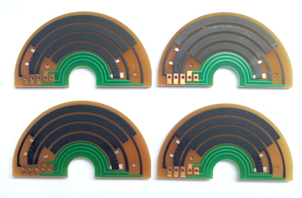
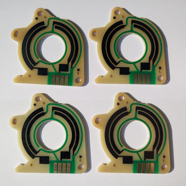
Thick Film Potentiometer PCB also calls Printed Carbon Potentiometer PCB is a new technology that will improve the process of embedded resistors by eliminating the need for special termination treatment, such as immersion silver,or silver palladium, gold palladium, Also speed up the laser trim process with tighter TCR’s; and increase the reliability performance with a stable binder system. Thus far, The environmental and mechanical testing of Printed Carbon Potentiometer PCB processing has also been successful. Continuing to test and formulate higher resistivity values will prove these thick film resistor technology has a future in the embedded passives market. On the other hand, Thick Film Potentiometer PCB values currently available for testing show good adhesion to a clean copper surface. This eliminates the need for silver immersion, or silver palladium, gold palladium which presents a cost savings as well as reduces concerns of silver migration. Thick Film Potentiometer PCB is to incorporate reliable carbon resistors printing inside the printed wiring boards using standard PCB processing. The printed resistor materials (thick film Ink) are based on a novel hydrophobic polyimide resin developed specifically to serve as a polymeric thick film resistors or thin film resistor material . this technology is quite mature,thick film inks can be printed on a wide range of substrates — from high temperature ceramics to common FR4 PCB materials,or Polyimide (PI) Flex PCB Material, or Ceramic PCB. For more information, Please refer to "Thick-Film-Resistors-PCB" Thick Film Resistor PCB CapabilitySubstrate Material : FR4, Alumina ( 96%AL2O3), PI (Polyimide), SUS304 Conductor material: Copper, Ag/Pd (Silver palladium) Thick Film thickness (height): 15um +/-5 um Minimum Thick Film Track Width: 0.2 mm +/-0.05 mm Minimum Thick Film Track Spacing (clearance): 0.2 mm Minimum covered width (Carbon to Copper) : 0.25mm (importance) Resistance range: can be from 100M ohms/square, 100K ohms/square, 10K ohm/square…. 10 ohms/square Resistance Tolerance: +/-10%(Standard), or less than +/-1% (Laser trimming) Resistance Linearity tolerance: < 1 % Carbon ink Durability (Life Time): 5 million minimum Temperature rating: -40℃/+125℃ More information, Please refer to "Thick Film Resistor PCB"
|
|
|
|